Language
ENG
Enter Keywords...

NEW
 Home / News / industy news / SAE flanges in hydraulic systems: design optimization and efficiency improvement
SAE flanges in hydraulic systems: design optimization and efficiency improvement
 2025.09.01
 industy news
1. Background Overview
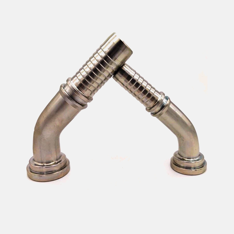
In hydraulic systems, SAE flanges (Society of Automotive Engineers Flange) are widely used connection standards for high-pressure hydraulic pipelines. Their primary role is to provide a reliable interface between hydraulic components such as pumps, valves, and cylinders.
Key Features of SAE Flanges
High Pressure Resistance
SAE flanges can withstand pressures from 100 bar to 350 bar or even higher in certain specialized systems, making them suitable for high-performance hydraulic applications.
Reliable Sealing
Sealing is achieved through O-rings or tapered surfaces. Proper sealing ensures minimal leakage under high-pressure conditions and prevents contamination.
Ease of Installation
SAE flanges are typically fastened with bolts, making assembly, disassembly, and maintenance convenient.
As hydraulic systems develop towards higher efficiency and lighter weight, optimizing SAE flange design is critical for improving overall system efficiency.
2. Common Problems of SAE Flanges
Leakage Risk
Leakage may occur due to uneven sealing surfaces, inconsistent bolt torque, or material mismatch causing differential expansion.
High Pressure Loss
Flow resistance can increase when the internal channel of the flange is rough, the bending angles are sharp, or local turbulence is significant, leading to reduced system efficiency.
Excessive Weight
Traditional steel flanges can add considerable weight, which is unfavorable in mobile or dynamic hydraulic systems.
Fatigue and Lifespan Issues
Continuous high-pressure pulsation can cause flange cracking or bolt loosening, affecting system reliability and maintenance cycles.
3. Design Optimization Strategies
3.1 Material Optimization
Using high-strength lightweight alloys, such as aluminum alloys or high-strength steel, can reduce weight while maintaining pressure resistance. Surface treatments like nickel plating or anodizing improve wear and corrosion resistance.
3.2 Fluid Dynamics Optimization
Design the internal flow paths with smooth transitions and avoid sharp corners. Computational Fluid Dynamics (CFD) simulations can help optimize the flow distribution inside the flange, reduce local turbulence, and minimize pressure drop.
3.3 Sealing Performance Optimization
Improve O-ring groove design to ensure uniform compression and sealing. Optimize bolt number and layout to reduce localized stress. Consider thermal expansion effects for high-temperature operations.
3.4 Structural Lightweighting
Design hollow or honeycomb structures in the flange to reduce material usage. Thin-wall high-strength designs maintain pressure capacity while decreasing weight.
4. Efficiency Improvement Measures
4.1 Reduce Hydraulic System Pressure Drop
Increase the internal diameter of flanges to prevent throttling. Minimize the resistance coefficient at flange connections to reduce energy loss.
4.2 Improve Assembly Efficiency
Use quick-tightening bolts and standardize flange dimensions for easier installation and maintenance.
4.3 Extend Maintenance Intervals
Employ wear-resistant sealing elements and corrosion-protected bolts and flange surfaces to prolong operational life.
4.4 Monitoring and Diagnostics
Integrate pressure sensors and leakage monitoring devices in high-pressure systems to detect potential flange issues early and maintain efficiency.
5. Practical Recommendations
CFD Simulation Priority
Perform fluid simulations in the design phase to optimize flow paths and prevent frequent adjustments during operation.
Standardization and Modularization
Use unified flange sizes wherever possible to simplify inventory management and reduce design complexity.
Material-Cost Balance
Lightweight materials can reduce system energy consumption, but cost-effectiveness should be considered when selecting alloys or surface treatments.
Dynamic Load Testing
Verify flange durability under vibration and pulsation conditions to ensure long-term reliability.
6. Optimization Strategy Table
| Optimization Aspect | Strategy | Expected Benefit |
|---|---|---|
| Material | High-strength alloys, surface treatment | Reduced weight, improved corrosion resistance |
| Fluid Dynamics | Smooth internal flow paths, CFD simulation | Lower pressure drop, improved flow efficiency |
| Sealing | Optimized O-ring groove, bolt layout | Reduced leakage risk, higher reliability |
| Structure | Hollow or honeycomb design, thin-wall construction | Lightweight while maintaining pressure capacity |


Custom hydraulic accessories
From concept to production, we can create the products you want
Products
Contact Information
-

Tel: +86-159-6851-8588
-

E-mail: [email protected]
-

Add:Zhu Jia Station Village, Diankou Town, Zhuji City , Zhejiang Province, China
