


Language
ENG
Enter Keywords...

NEW
 Home / News / industy news / The Complete Guide to Hydraulic Hose Connectors: Types, Selection & Installation
The Complete Guide to Hydraulic Hose Connectors: Types, Selection & Installation
 2026.07.06
 industy news
What Are Hydraulic Hose Connectors — and Why Do They Matter?
Hydraulic hose connectors are the mechanical interface between a hydraulic hose and the rest of a fluid power system. They seal, secure, and transmit pressurized fluid between pumps, cylinders, valves, and actuators. Get them wrong — wrong size, wrong thread, wrong pressure rating — and the result is leaks, downtime, or catastrophic system failure.
In industrial and mobile hydraulic systems, over 80% of hydraulic failures are traced back to hose and fitting issues — including incorrect connector selection, improper installation, and incompatible thread types. Understanding hydraulic hose & fittings is not optional for engineers, technicians, or procurement managers — it is foundational.
This guide covers everything: what is hydraulic hose, the main types of hydraulic connectors, how to read a hydraulic hose fittings chart, how to match hydraulic fitting sizes, and how to install hyd hose fittings correctly the first time.
What Is Hydraulic Hose? A Foundation Before the Fittings
Before selecting connectors, it is essential to understand what is hydraulic hose at a structural level. A hydraulic hose is a flexible, high-pressure conduit designed to carry hydraulic fluid — typically oil — between components in a hydraulic system. Unlike rigid hydraulic pipe fittings and hard lines, hoses accommodate vibration, movement, and misalignment.
A standard hydraulic hose has three layers:
- Inner tube: Synthetic rubber or PTFE that contacts the fluid and must be chemically compatible with it.
- Reinforcement layer: One or more braided or spiral-wound layers of high-tensile steel wire or textile fiber that give the hose its pressure rating.
- Outer cover: Abrasion-resistant rubber or thermoplastic that protects against environmental damage.
The types of hydraulic hose vary by construction, pressure rating, and application. The most common standards are SAE J517 (North America) and EN 853/856/857 (Europe/international). Pressure ratings range from under 1,000 PSI for low-pressure return lines to over 6,000 PSI for high-pressure spiral hoses used in heavy equipment.
Common Types of Hydraulic Hose by Construction
| Hose Type | Reinforcement | Typical Pressure Range | Common Application |
|---|---|---|---|
| SAE 100R1 | 1 wire braid | Up to 2,750 PSI | General hydraulic lines |
| SAE 100R2 | 2 wire braid | Up to 4,000 PSI | Medium-high pressure systems |
| SAE 100R9 | 4 spiral wire | Up to 5,800 PSI | Heavy equipment, mining |
| SAE 100R7 | Textile braid | Up to 1,500 PSI | Low-pressure return/suction |
| PTFE-lined (R14) | SS braid | Up to 3,000 PSI | Chemical, food, high-temp |
Types of Hydraulic Connectors: The Full Breakdown
Understanding the types of hydraulic connectors is the most critical step in system design. Connectors — also called hyd hose fittings, hose ends, or hydraulic hose ends types — vary by thread form, sealing method, and pressure class. Mixing incompatible types is one of the most common and dangerous mistakes in hydraulic system assembly.
NPT — National Pipe Taper
NPT threads seal by thread engagement and thread sealant (PTFE tape or pipe dope). They are common in North American plumbing and low-to-medium pressure hydraulic systems. Maximum recommended working pressure: 2,000 PSI for steel fittings. NPT is not ideal for high-vibration or high-cycle applications because repeated assembly/disassembly degrades the thread seal.
BSPP (G) — British Standard Parallel Pipe
BSPP is a parallel thread that seals with a soft seal (O-ring or bonded washer) at the face. It is the dominant thread form in European, Asian, and international hydraulic equipment. BSPP fittings are more reliable for hydraulic hose connections than NPT at elevated pressures and offer a leak-free metal-to-elastomer seal. Rated to 3,000–5,000 PSI depending on fitting size and material.
BSPT — British Standard Taper Pipe
Similar to NPT in concept (tapered thread seal), but with different thread geometry — 55° thread angle vs. NPT's 60°. BSPT and NPT are not interchangeable even though they can sometimes appear to thread together partially, creating a false sense of assembly. This cross-threading scenario is a leading cause of hydraulic hose connection failures.
JIC — Joint Industry Council (37° Flare)
JIC fittings use a 37° flared cone seat to create a metal-to-metal seal. They are widely used in North American aerospace, defense, and industrial hydraulic systems. JIC hose connection types are vibration-resistant, reusable, and rated up to 5,000 PSI in many sizes. They are specified under SAE J514 and are often used with 1/2 hydraulic hose fittings in mid-range applications.
ORFS — O-Ring Face Seal
ORFS is considered the gold standard for zero-leak hydraulic connections. The O-ring sits in a groove on the flat face of the male fitting and compresses against the female port face. ORFS fittings are rated up to 6,000 PSI and are the preferred choice for high-pressure, high-vibration applications in mobile machinery and offshore equipment. They are specified under SAE J1453.
SAE Straight Thread O-Ring (ORB)
ORB fittings use a straight thread with an O-ring that seals in a chamfered port. They are common as port connections on hydraulic valves, pumps, and cylinders. Unlike ORFS, the sealing happens at the boss (port), not the face. ORB is defined under SAE J1926 and works at pressures up to 6,000 PSI.
Metric DIN Fittings (24° Cone)
DIN 2353 (also called "bite-type" or "compression" fittings) and DIN 7631 cone fittings are dominant in European hydraulic pipe connections. They offer a 24° internal cone seal and are used extensively in hydraulic pipe fittings and tube assemblies on European-made machinery. Working pressure can exceed 5,800 PSI for small-bore stainless versions.
Flat-Face Quick-Disconnect Couplers
These are a specialized category of industrial hose connector types that allow tool-free connect and disconnect under low or zero pressure. Flat-face couplers minimize fluid spillage — critical in environmentally sensitive applications. They are common on agricultural equipment, skid steers, and loader attachments. Flat-face designs can reduce spillage by up to 98% compared to older poppet-style couplers.
Hydraulic Hose Fittings Chart: Thread ID at a Glance
One of the most frequent questions in the field is: "How do I know which fitting type this is?" A hydraulic hose fittings chart provides a fast visual and dimensional reference. The key identifiers are thread pitch, thread angle, seat angle, and O-ring presence.
| Fitting Type | Thread Form | Thread Angle | Seat/Seal Type | Max PSI (typical) |
|---|---|---|---|---|
| NPT | Tapered | 60° | Thread sealant | 2,000 |
| BSPP (G) | Parallel | 55° | Bonded washer / O-ring face | 5,000 |
| BSPT | Tapered | 55° | Thread engagement | 2,500 |
| JIC (37°) | UN/UNF straight | 60° | 37° flare metal-to-metal | 5,000 |
| ORFS | UN/UNF straight | 60° | Flat face O-ring | 6,000 |
| ORB (SAE) | UNF straight | 60° | O-ring at boss | 6,000 |
| DIN 24° Cone | Metric | 60° | 24° internal cone | 5,800 |
Pro tip: When identifying an unknown fitting in the field, always measure thread OD with a caliper and thread pitch with a pitch gauge before assuming the type. Visual inspection alone causes misidentification in over 30% of cases according to field service surveys.
Hydraulic Fitting Sizes: How the Dash System Works
Hydraulic hose & fittings use a "dash number" system to indicate hose inner diameter in 1/16-inch increments. This is the universal sizing language across SAE-standard hydraulic hoses fittings and hyd hose ends in North America and increasingly worldwide.
- -4 dash: 4/16" = 1/4" ID
- -6 dash: 6/16" = 3/8" ID
- -8 dash: 8/16" = 1/2" ID — the most common size in mobile equipment
- -10 dash: 10/16" = 5/8" ID
- -12 dash: 12/16" = 3/4" ID
- -16 dash: 16/16" = 1" ID
- -20 dash: 20/16" = 1-1/4" ID
- -24 dash: 24/16" = 1-1/2" ID
- -32 dash: 32/16" = 2" ID
1/2 hydraulic hose fittings (-8 dash) are by far the most widely used size in agriculture, construction, and industrial equipment. When specifying a hose assembly, you need the dash size for both the hose and the fittings — they must match. A -8 hose takes -8 hyd hose ends; you cannot crimp a -6 end onto a -8 hose body.
Note that hydraulic fitting sizes refer to hose bore, not thread size. A 1/2" hose (-8) can have a 9/16"-18 UNF JIC thread or a 3/4"-16 UNF ORB thread on the same hose end — the thread is a separate dimension from the hose bore.
Hydraulic Fitting Sizes Reference Table
| Dash Size | Hose ID (inch) | JIC Thread (typical) | ORB Thread (typical) | ORFS Thread (typical) |
|---|---|---|---|---|
| -4 | 1/4" | 7/16"-20 | 7/16"-20 | 9/16"-18 |
| -6 | 3/8" | 9/16"-18 | 9/16"-18 | 11/16"-16 |
| -8 | 1/2" | 3/4"-16 | 3/4"-16 | 7/8"-14 |
| -10 | 5/8" | 7/8"-14 | 7/8"-14 | 1-1/16"-12 |
| -12 | 3/4" | 1-1/16"-12 | 1-1/16"-12 | 1-5/16"-12 |
| -16 | 1" | 1-5/16"-12 | 1-5/16"-12 | 1-5/8"-12 |
Types of Hose Fittings: Crimp, Reusable, and Swaged
Beyond thread type, hydraulic hose ends types are also classified by how they attach to the hose body. This is a critical distinction for field repair, cost management, and performance under pressure cycling.
Crimped Fittings
Crimped fittings are the industry standard for high-pressure hydraulic hose assemblies. A hydraulic crimping machine compresses a metal ferrule around the hose body and fitting stem with precise, measured force. Crimped assemblies can withstand 4x the working pressure in burst tests when assembled to manufacturer specifications. They are permanent — once crimped, they cannot be disassembled and reused.
All major OEM hydraulic hose assemblies — Caterpillar, John Deere, Parker, Gates — use crimped hydraulic hoses fittings as the default construction method.
Reusable (Field-Attachable) Fittings
Reusable hyd hose fittings thread onto the hose without a crimping machine, making them popular for field emergency repairs. They consist of a nipple that inserts into the hose bore and a socket that screws over the hose exterior, compressing it between the two components.
The trade-off: reusable fittings typically have a 20–25% lower pressure rating than equivalent crimped assemblies and are not recommended for high-pressure spiral hose. They are best suited to -4 through -12 sizes on braided hose in non-critical applications.
Swaged Fittings
Swaging is similar to crimping but uses a different mechanical process — dies push inward from multiple sides simultaneously rather than through a radial crimp. Swaged hose ends are common in aerospace and defense hydraulic systems where tolerances are extremely tight. For industrial hydraulic pipe connections, crimping is more prevalent.
Bite-to-the-Wire Fittings
Some fitting designs, particularly for high-pressure spiral hose, are engineered to bite through the outer cover and into the wire reinforcement during crimping. This "bite-to-the-wire" design ensures the fitting engages the structural element of the hose, not just the rubber outer. These are required for 4- and 6-wire spiral hose above 5,000 PSI.
Hydraulic Pipe Fittings vs. Hose Fittings: Key Differences
Many engineers and technicians use "hydraulic pipe fittings" and "hydraulic hose fittings" interchangeably, but they serve different functions and are not interchangeable in practice.
- Hydraulic pipe fittings connect rigid steel or stainless tubing (hard lines). They include compression fittings, flared tube fittings, and threaded pipe nipples used in hydraulic pipe connections inside control blocks, manifolds, and machine frames where vibration is minimal.
- Hydraulic hose fittings terminate flexible rubber or thermoplastic hose. They include the crimp socket and fitting nipple that anchor the hose end to a threaded port or coupling.
A complete hydraulic circuit typically uses both types — rigid pipe or tubing inside panels and frames, with flexible hose sections at actuators, motors, and moving joints. Understanding when to use which is a system design skill. As a rule: anywhere relative motion exists between two connected components, use hose. Everywhere else, hard lines are preferred for lower cost, higher reliability, and less maintenance.
Hydraulic pipe connections using tube fittings (DIN, Parker CPI, Swagelok-style) are especially common in European machinery, process plants, and offshore platforms where cleanliness and leak-free performance are mandatory.
How to Select the Right Hydraulic Hose Connections for Your System
Choosing hydraulic hose connections is a structured engineering decision, not a guessing exercise. Use this framework — sometimes called the STAMPED method — to specify any hose assembly correctly.
S — Size
Match hose ID to system flow requirements. Undersized hoses cause excessive pressure drop and heat buildup. Use this guideline: for pressure lines, target fluid velocity of 10–15 ft/sec; for return lines, 5–10 ft/sec; for suction lines, 2–4 ft/sec. Flow rate and target velocity determine the required ID via Q = A × V.
T — Temperature
Both the fluid temperature and ambient temperature affect hose selection. Standard nitrile rubber hose is rated from -40°F to +212°F. For higher temperatures, PTFE-lined hose or high-heat compounds rated to +300°F may be needed. At the connectors, O-ring material matters: Buna-N (nitrile) suits petroleum-based fluids; Viton handles higher temperatures and synthetic fluids.
A — Application and Routing
Consider bending radius — a hose bent tighter than its minimum bend radius loses up to 87% of rated working pressure capacity. Use elbow fittings (45° or 90° hyd hose ends) to avoid sharp bends at ports. Leave 10–15% slack in routing to account for length change under pressure (hoses can shorten or lengthen up to 4% at full pressure).
M — Material Compatibility
Fluid compatibility is non-negotiable. Petroleum-based hydraulic oil works with most standard nitrile inner tubes. But water-glycol fire-resistant fluids, phosphate ester fluids (Skydrol), and biodegradable vegetable-oil fluids each require specific inner tube compounds. Always confirm compatibility with the hose manufacturer's chemical resistance chart.
P — Pressure
The hose assembly — hose, fittings, and crimp — must be rated for the system's maximum working pressure, including pressure spikes. Hydraulic systems can experience pressure spikes 2–3x the static working pressure during rapid valve actuation. Always choose hose assemblies rated at or above the worst-case peak pressure, not just the nominal working pressure.
E — Ends (Fitting Type and Thread)
Identify the port thread type on the mating component (valve, cylinder, pump) using a thread identification kit or hydraulic hose fittings chart. Then select the correct mating fitting — JIC, ORFS, BSPP, ORB, etc. — in the same dash size as the hose. When in doubt, default to ORFS for new designs; it is the easiest to seal and the most leak-resistant.
D — Delivery (Length, Orientation)
Measure the routed length with a string or flexible tape, not point-to-point distance. Account for fitting orientation — specify the clock position of swivel fittings (e.g., 90° elbow pointing at 3 o'clock) to ensure proper routing without hose twist. Twisted hose has reduced flex life and can fail up to 70% sooner than properly routed assemblies.
Industrial Hose Connector Types for Special Applications
Standard hydraulic hose & fittings cover the majority of applications, but certain industries require specialized industrial hose connector types with unique performance characteristics.
High-Temperature Applications
Steel mills, foundries, and industrial ovens require hose assemblies rated above +300°F. PTFE-lined hose with stainless steel fittings is the standard solution. PTFE is chemically inert and rated to +450°F continuously. Fittings in these assemblies use all-stainless bodies with Viton O-rings or PTFE backup rings.
Subsea and Offshore Hydraulic Connections
Hydraulic hose connections in subsea environments must resist external seawater pressure, internal system pressure, and marine corrosion simultaneously. Duplex stainless steel fittings and thermoplastic hose with nylon covers are typical. Flat-face quick-disconnect couplers with wet-mate capability allow connect/disconnect under water pressure.
Food and Pharmaceutical Grade
Applications where hydraulic fluid contact with food or pharmaceutical products is possible require FDA-compliant inner tube materials and stainless steel hose connection types. 316 stainless steel fittings with electropolished interiors and sanitary tri-clamp end connections are standard. Hose assemblies in food plants undergo CIP (clean-in-place) cycles at 180°F — requiring hose-to-fitting crimp integrity that holds under repeated thermal cycling.
Mining and Tunneling
Underground mining equipment faces abrasion, crush loads, and fire-resistant fluid requirements. Mining-spec hydraulic hoses fittings use abrasion-resistant outer covers rated to 10x standard abrasion resistance, stainless steel or zinc-nickel plated carbon steel fittings, and are compatible with water-glycol HFC or HFD fluid types mandated by mine safety regulations in most jurisdictions.
Step-by-Step Hydraulic Hose Connector Installation
Correct installation of hydraulic hose & fittings is as important as correct selection. Even a perfectly specified hose assembly will fail prematurely if installed improperly. Follow this process for every assembly.
- Verify the assembly specification. Confirm hose type, dash size, fitting type, thread, and end configuration match the system requirements before beginning.
- Cut the hose square. Use a dedicated hose cutting wheel or saw — never a utility knife or grinder. A non-square cut causes uneven crimp ferrule seating. Cap or tape cut ends immediately to prevent contamination.
- Mark the insertion depth. Before inserting the fitting nipple, mark the correct insertion depth on the hose OD with a paint marker. This confirms the hose is fully seated before crimping.
- Insert the fitting and verify seating. Push the hose fully onto the nipple until the mark disappears into the ferrule. Inspect visually — if the hose is not fully seated, the crimp will have uneven wall engagement.
- Set the correct die and crimp diameter. Use the hose manufacturer's crimp specification table for the specific hose/fitting combination. Crimp diameter tolerance is typically ±0.010" — exceeding this range causes either under-crimp (leak/blowoff) or over-crimp (hose damage).
- Measure the crimped ferrule OD. With a crimp gauge, verify the crimped OD matches the specification. Document the measurement for quality records.
- Flush the assembly before installation. Internal contamination is the number-one cause of hydraulic component damage. Flush new hose assemblies with clean, filtered hydraulic fluid before installing in the system.
- Install without twisting. Route the hose, then tighten fittings with two wrenches — one to hold the hose end, one to torque the nut. Never spin the hose to thread the fitting.
- Torque fittings to specification. Use a torque wrench. For ORFS and ORB, follow SAE J1453/J1926 torque tables. For JIC, use flat-to-flat turn method (1 flat = 60°) after hand-tight. Over-torquing crushes O-rings and causes fitting cracking; under-torquing leaves the joint leak-prone.
- Pressure test before returning to service. Hydrostatically test the assembled circuit at 1.5x working pressure for 30–60 seconds. Inspect all hydraulic hose connections for weeping, bulging, or movement before declaring the assembly fit for service.
Common Hydraulic Hose Connector Failures and How to Prevent Them
Understanding failure modes makes it possible to prevent them systematically. These are the most frequent failure modes seen in hydraulic hoses fittings across industrial and mobile equipment.
Fitting Blowoff
The hose separates from the fitting under pressure — the most dangerous failure mode. Causes: under-crimped ferrule, wrong crimp die, hose not fully seated before crimp, or reusable fitting used on a hose beyond its rated diameter. Hose blowoff at 3,000 PSI releases fluid at over 600 mph — capable of causing injection injuries that require emergency surgery. Prevention: follow crimp specifications exactly, verify insertion depth, test at 1.5x working pressure.
Thread Leakage at Hydraulic Pipe Connections
NPT and BSPT threads leak when over- or under-torqued, or when PTFE tape is wrapped in the wrong direction. ORFS and ORB fittings leak when O-rings are pinched, omitted, or of the wrong durometer. Prevention: always verify O-ring is seated correctly before torquing; for tapered threads, apply fresh sealant to the male thread only, leaving the first 1–2 threads clean.
Hose Abrasion and External Damage
Hose contact with sharp edges, hot surfaces, or adjacent moving parts abrades the outer cover, eventually exposing the wire reinforcement to corrosion and fatigue. Abrasion is the leading cause of premature hose failure in mobile equipment. Prevention: use clamps, sleeves, or spring guards at contact points; route away from heat sources above 212°F.
Hose Twist and Torsion
A hose twisted during installation has misaligned reinforcement braid, which significantly reduces pressure capacity and flex life. Even 5° of twist reduces hose life noticeably; 10° of twist can reduce rated pressure by 70%. Prevention: use swivel fittings at one or both ends; install with yellow lay line straight and untwisted.
Wrong Fitting Type — Thread Cross-Coupling
NPT and BSPT threads are not compatible despite appearing similar. JIC 37° and DIN 24° cone fittings are not interchangeable. Cross-coupling creates a false assembly that may hold briefly but will leak or blow out under operating pressure. Use a thread pitch gauge and OD micrometer to positively identify every unknown fitting before assembly.
Hydraulic Hose Connector Materials: Choosing the Right Metal
The material of hyd hose fittings affects corrosion resistance, weight, pressure rating, and cost. The four main materials are:
| Material | Corrosion Resistance | Pressure Rating | Cost | Best Use Case |
|---|---|---|---|---|
| Carbon Steel (zinc-plated) | Moderate | High | Low | General industrial, indoor, mobile equipment |
| Stainless Steel 304 | High | High | Medium | Outdoor, washdown, food processing |
| Stainless Steel 316 | Very High | High | High | Marine, offshore, chemical plant |
| Brass | Good | Medium (max ~3,000 PSI) | Medium | Low-medium pressure, pneumatics, instrumentation |
Carbon steel with zinc-nickel plating offers the best corrosion protection for standard hydraulic pipe fittings and hose ends in industrial environments, outperforming traditional zinc plating by 3–5x in salt spray testing (500+ hours vs. 96–120 hours for standard zinc plate).
Maintenance and Inspection of Hydraulic Hose & Fittings
Proper maintenance extends the service life of hydraulic hose connections significantly and prevents unplanned downtime. Industry standards — including ISO 4413 and SAE J1273 — mandate regular inspection intervals for all hydraulic hose assemblies.
Visual Inspection Checklist (Every Service Interval or 250 Hours)
- Check for fluid seepage at hyd hose ends — even a small weep indicates fitting or O-ring degradation.
- Inspect outer cover for cuts, abrasion, blistering, or hardening — hardening indicates heat damage.
- Check for hose kinking or tight bends — correct routing or add slack before next operation.
- Inspect hydraulic pipe fittings and hydraulic pipe connections for corrosion, especially at the ferrule-to-fitting interface.
- Verify hose clamps and brackets are secure and not cutting into hose covers.
- Check hose age tag — most OEMs recommend replacing hydraulic hose assemblies every 6 years regardless of appearance, with an overall service limit of 10 years from date of manufacture per ISO 6945.
When to Replace Immediately
- Any active fluid leak at the fitting or along the hose body.
- Exposed wire reinforcement anywhere on the hose.
- Hose blistering or bubbling under the outer cover.
- Crushed or kinked hose that has been operated in that condition.
- Any hose assembly involved in a pressure spike event above its rated burst pressure.
Quick Reference: Hose Connection Types Summary
For fast field reference, here is a condensed summary of the primary hose connection types and their identifying characteristics.
| Connection Type | Key Identifier | Seal Method | Reusable? | Ideal For |
|---|---|---|---|---|
| JIC 37° | 37° cone, UNF thread | Metal-to-metal flare | Yes | General industrial, aerospace |
| ORFS | Flat face, O-ring groove visible | O-ring face seal | Yes (replace O-ring) | High pressure, vibration, zero-leak |
| NPT | Tapered thread, no seat | Thread sealant | Yes (limited cycles) | Low-medium pressure, plumbing |
| BSPP | Parallel, 55° thread, washer seat | Bonded washer | Yes (replace washer) | European equipment, international |
| ORB (SAE) | UNF straight, chamfered boss port | O-ring at boss | Yes | Valve/pump/cylinder ports |
| DIN 24° Cone | Metric thread, 24° internal cone | Cone compression | Yes | European tube/pipe connections |
| Quick-Disconnect (Flat Face) | Push-to-connect, no tools needed | Internal poppet + O-ring | Yes (coupler reused) | Attachments, ag equipment, skid steers |
Final Takeaways: Getting Hydraulic Hose Connectors Right
Hydraulic hose connectors are small components that carry enormous responsibility. A single failed fitting in a 5,000 PSI system can cause equipment loss, environmental contamination, or serious personal injury. Getting them right requires understanding the full system: hose construction, fitting geometry, thread standards, pressure ratings, fluid compatibility, and installation procedure.
The key principles to take away:
- Match thread types precisely — NPT, BSPT, JIC, ORFS, BSPP, and ORB are not interchangeable.
- Use the dash size system to communicate hose and fitting sizes unambiguously, especially for 1/2 hydraulic hose fittings (-8) and adjacent sizes.
- Always crimp to specification — verify crimp diameter after every assembly.
- Use ORFS for new designs where possible — it is the highest-performing, most leak-resistant hose connection type available in standard catalog sizes.
- Inspect on schedule — replace hose assemblies by age and condition, not just when they fail visibly.
- Choose materials for environment — carbon steel for general use, 316 stainless for marine or aggressive chemical environments.
Whether you are specifying hydraulic hose & fittings for a new machine, repairing field equipment, or building a hydraulic power unit from scratch, applying this guide's principles will result in safer, longer-lasting, and more reliable hydraulic hose connections every time.

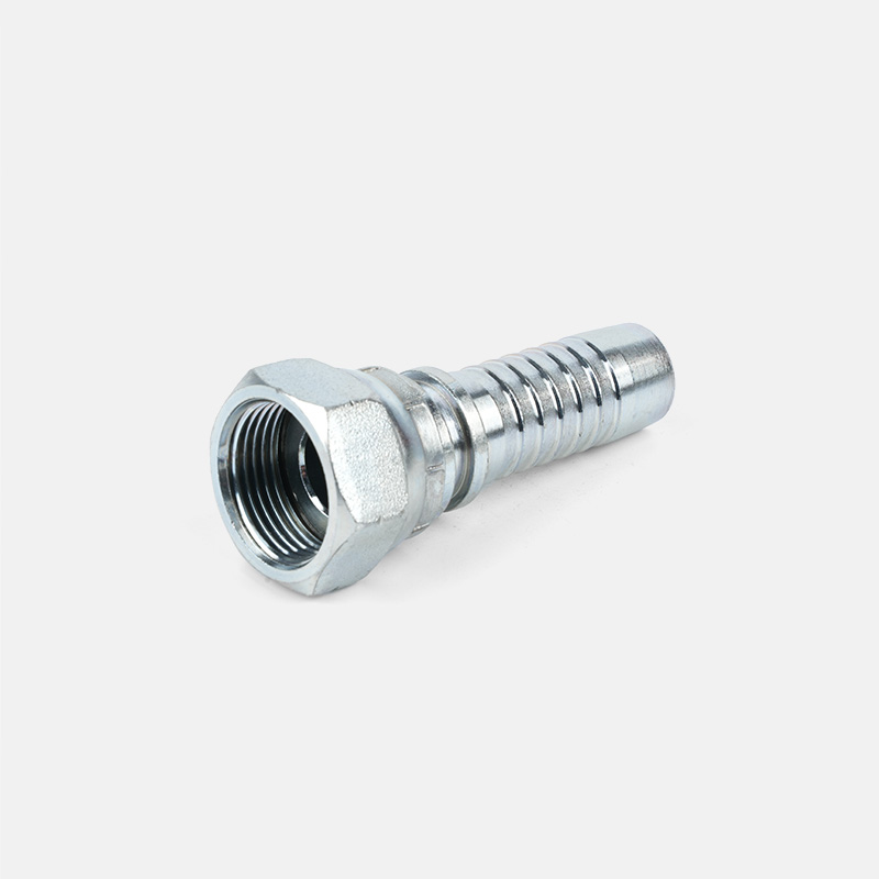
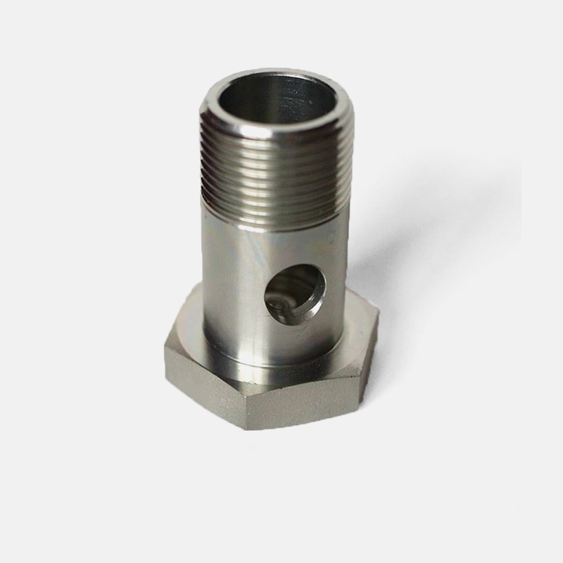
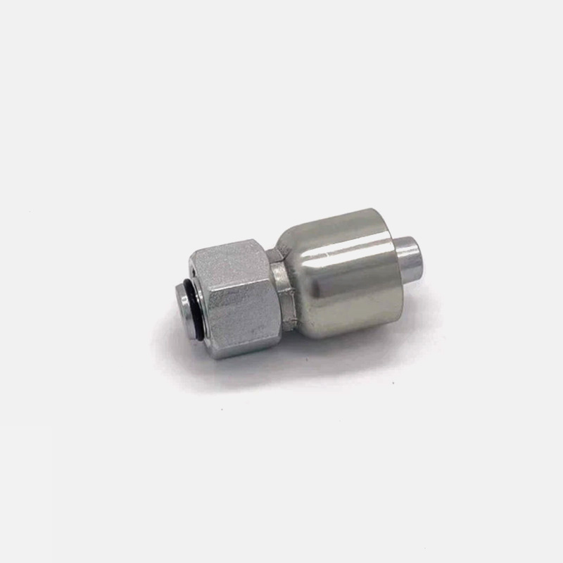
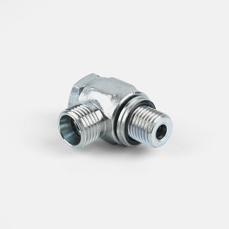
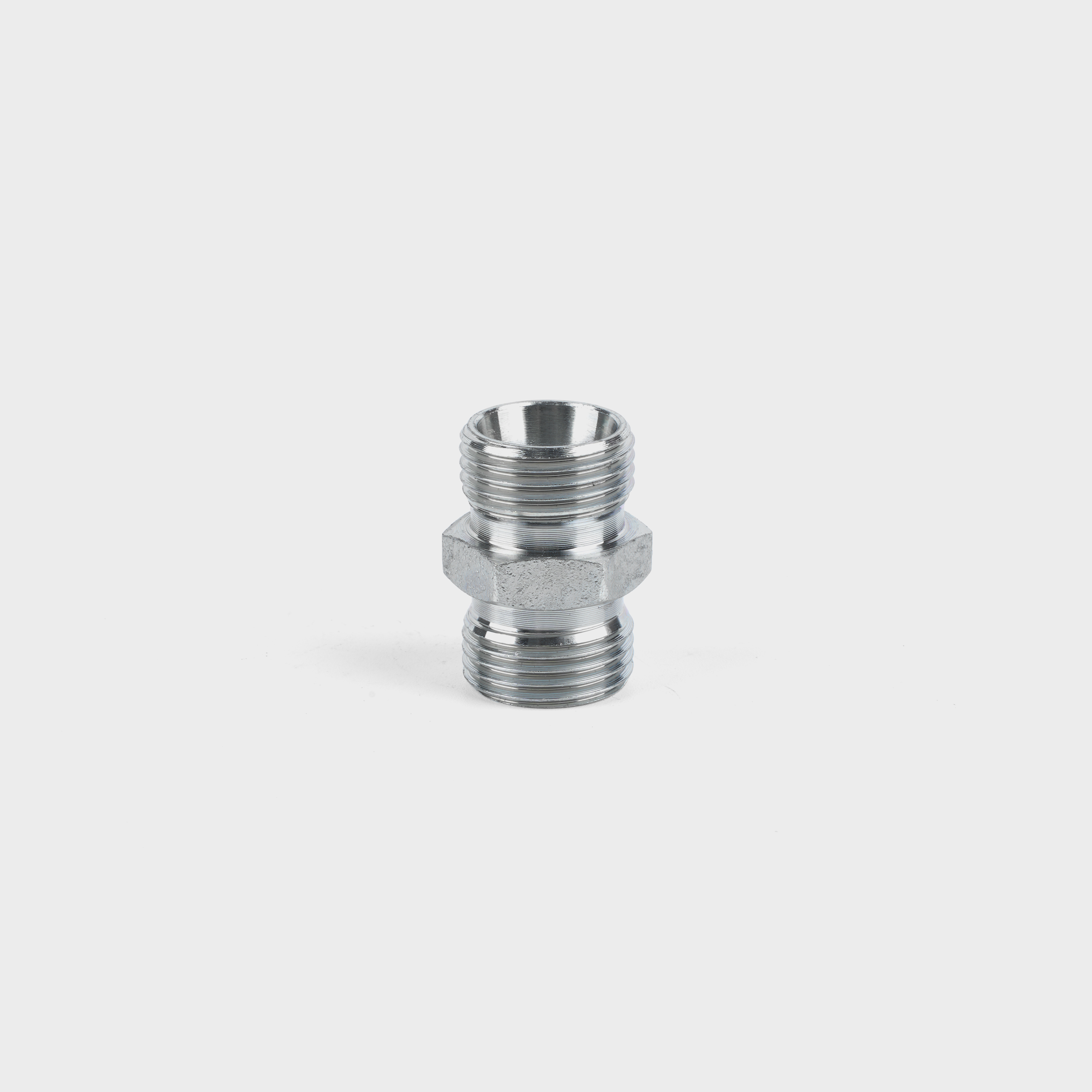
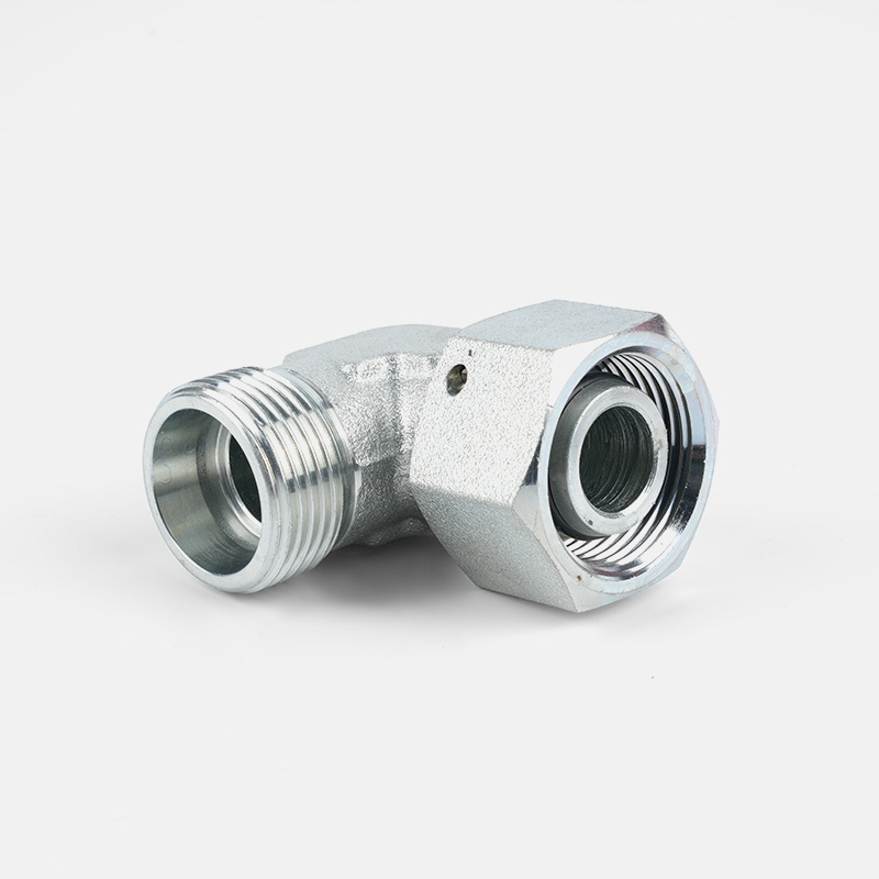
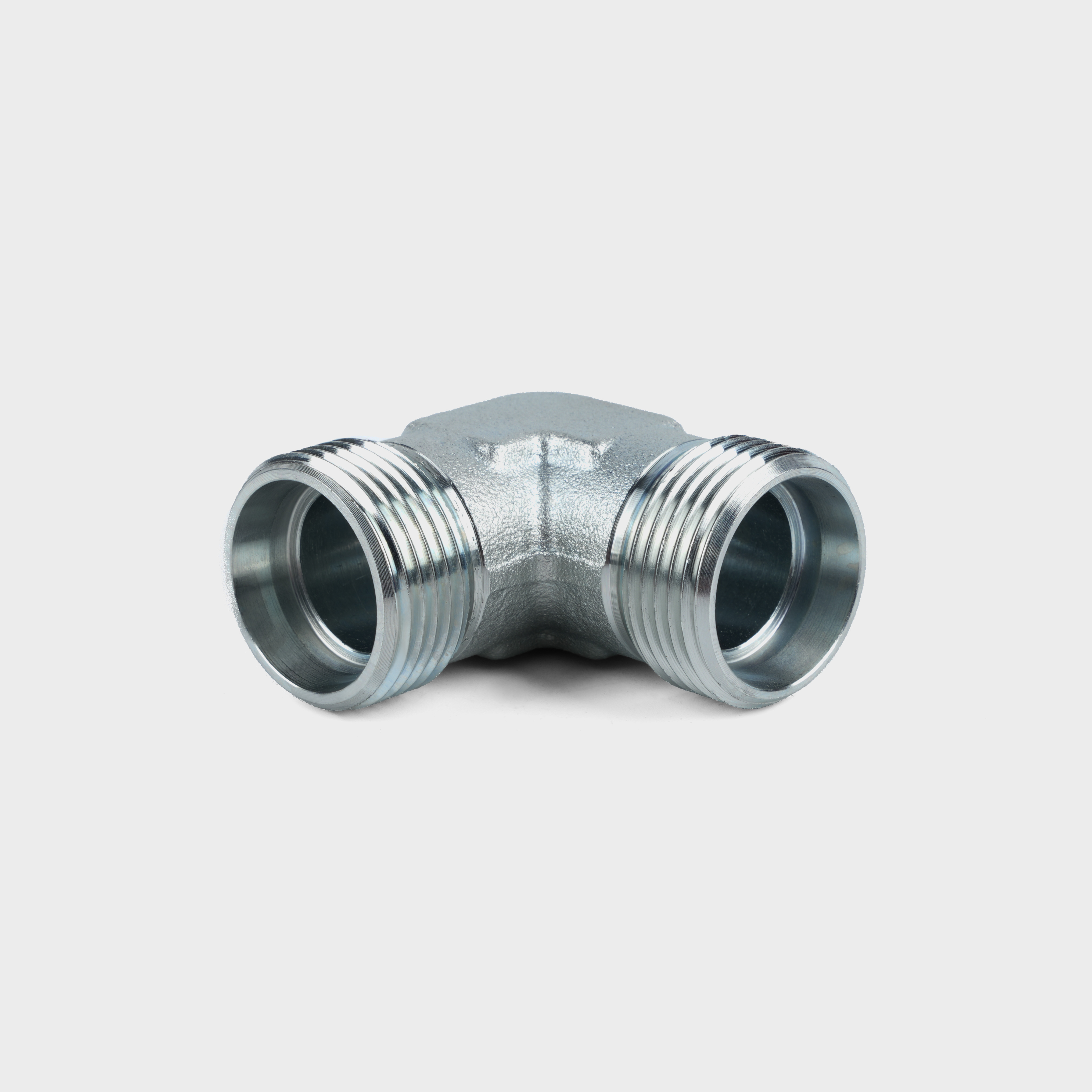

Custom hydraulic accessories
From concept to production, we can create the products you want
Products
Contact Information
-

Tel: +86-159-6851-8588
-

E-mail: [email protected]
-

Add:Zhu Jia Station Village, Diankou Town, Zhuji City , Zhejiang Province, China
