Language
ENGWhat’s the Difference Between SAE Flanges and DIN Flanges in Hydraulic Systems?
 2025.11.03
 industy news
Introduction: Understanding Hydraulic Flange Standards
Hydraulic systems are designed to handle high-pressure fluid power, and every connection within these systems must be strong, secure, and leak-free. One of the most important components ensuring this integrity is the hydraulic flange. These flanges connect pipes, hoses, or tubes and allow for easy assembly, disassembly, and maintenance.
There are several international standards for hydraulic flanges, but two of the most widely used are the SAE flanges and DIN flanges. Each follows a different design philosophy and is associated with specific regional and industrial preferences. Understanding their differences is crucial for engineers, technicians, and buyers who need to ensure compatibility and reliability in hydraulic applications.
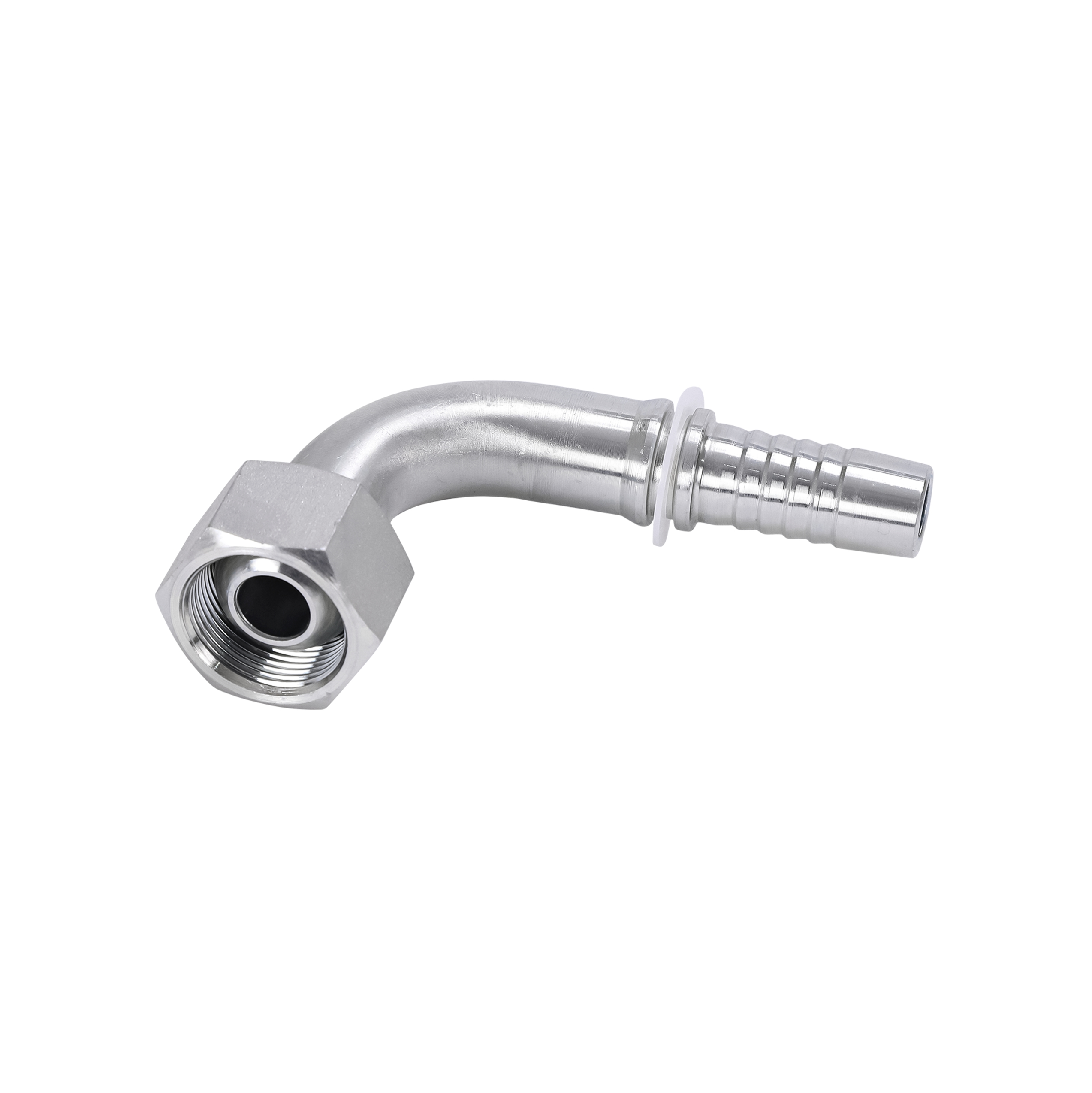
What Is an SAE Flange?
Definition and Standard
The SAE flange** is defined under the SAE J518 standard, which corresponds to the international ISO 6162 specification. It is one of the most common flange types used in North American hydraulic systems. SAE flanges are typically used in medium to high-pressure hydraulic applications**, ensuring leak-proof connections in demanding environments such as mobile hydraulics, construction machinery, and industrial equipment.Pressure Ratings and Types
SAE flanges come in two main pressure categories:- SAE Code 61 – Standard pressure flanges rated for up to approximately 3,000 psi (207 bar).
- SAE Code 62 – High-pressure flanges rated for up to approximately 6,000 psi (414 bar).
The main difference between Code 61 and Code 62 flanges lies in the thickness of the flange head and the bolt pattern, which provide additional strength for high-pressure environments.
Design Features
SAE flanges use a four-bolt split clamp connection** and an O-ring face seal that ensures a tight, leak-free fit. The use of inch-based threads (UNC or UNF)** makes them particularly suited for equipment manufactured in North America.SAE flanges are also available in different configurations such as welded flanges, socket welds, and threaded connections, giving engineers flexibility in system design.
What Is a DIN Flange?
Definition and Standard
The DIN flange follows the DIN 20066 and ISO 6164 standards, commonly used in European hydraulic systems. DIN stands for Deutsches Institut für Normung, meaning the German Institute for Standardization.These flanges are known for their metric-based dimensions and compatibility with European hydraulic equipment, particularly in manufacturing, marine, and industrial automation sectors.
Pressure Capacity and Construction
DIN flanges are generally designed for medium to very high-pressure applications, with pressure ratings that can reach up to 6,300 psi (435 bar) or even higher depending on the specific standard and material.They can be found in weld-on, screw-on, and block flange configurations, each designed to handle specific types of mechanical stress and system layouts.
Design Characteristics
Unlike SAE flanges, DIN flanges use metric bolts and bolt holes, and their dimensions differ significantly even if the internal flow capacity appears similar. This makes direct interchangeability between DIN and SAE flanges impossible without adapters.DIN flanges are often made from high-strength carbon steel or stainless steel, providing excellent resistance to corrosion and fatigue in industrial settings.
Key Differences Between SAE and DIN Flanges
The following table summarizes the major technical and design differences between SAE and DIN hydraulic flanges:
| Feature | SAE Flange | DIN Flange |
| Standard | SAE J518 / ISO 6162 | DIN 20066 / ISO 6164 |
| Thread Type | Inch-based (UNC/UNF) | Metric-based threads |
| Pressure Rating | Code 61: up to ~3,000 psi Code 62: up to ~6,000 psi |
Typically up to ~6,300 psi |
| Design | 4-bolt split clamp with O-ring seal | 4-bolt or solid flange with metric bolts |
| Common Region | North America | Europe |
| Compatibility | Not interchangeable with DIN | Not interchangeable with SAE |
Practical Implications
Because the standards differ in dimensions, bolt hole patterns, and thread types, an SAE flange cannot directly replace a DIN flange and vice versa. Attempting to connect the two could result in leakage, misalignment, or component damage. Therefore, always verify system specifications and use proper adapters if cross-standard connection is unavoidable.
How to Choose Between SAE and DIN Flanges
Consider Equipment Origin
If your equipment is manufactured in North America, it will most likely follow SAE standards. Conversely, European-made machinery typically uses DIN standards. Matching the flange type to the system’s original design ensures correct fit and function.Evaluate Pressure Requirements
High-pressure systems (above 3,000 psi) often benefit from SAE Code 62 or DIN high-pressure flanges. Check the system’s working pressure and safety margin before making a selection.Check Thread Compatibility
SAE flanges use inch-based threads, while DIN uses metric threads. This affects not only the bolts but also the adapters and fittings connected to the system. Always verify thread compatibility before installation.Consult Manufacturer Documentation
Each hydraulic manufacturer may have specific design tolerances or compatibility recommendations. Always refer to the OEM’s documentation or system schematics before purchasing or installing flanges.
Can You Mix SAE and DIN Components?
Compatibility Challenges
Mixing SAE and DIN components is not recommended due to differences in thread type, bolt hole pattern, and pressure rating. Doing so may lead to improper sealing and potential leaks under high pressure.However, conversion adapters are available for certain systems where cross-standard connections are unavoidable. These adapters allow for secure transitions between SAE and DIN interfaces but should only be used in low-to-medium pressure situations and with professional guidance.
Safety Considerations
Always ensure that pressure limits are not exceeded when mixing standards. Use O-ring seals and proper torque levels to maintain joint integrity. Periodic inspection and pressure testing should be conducted after installation.
Choosing the Right Standard for Your Hydraulic System
Both SAE and DIN flanges serve the same fundamental purpose — to create a strong, leak-free hydraulic connection. However, they differ in design standards, regional use, and technical specifications.
When selecting a flange type, always consider:
- The origin of the equipment (US vs. EU)
- The system pressure and application
- The thread compatibility and bolt dimensions
Choosing the correct standard ensures a reliable, long-lasting hydraulic system that operates safely and efficiently. For complex installations or mixed systems, consult with a qualified hydraulic specialist or authorized supplier to verify compatibility and select the best flange configuration.


