


Language
ENG
Enter Keywords...

NEW
 Home / News / industy news / Code 62 Flange Guide: 6000 PSI SAE Flange Dimensions, Ratings & Selection
Code 62 Flange Guide: 6000 PSI SAE Flange Dimensions, Ratings & Selection
 2026.11.09
 industy news
A Code 62 flange is the four-bolt, flat-face hydraulic connection that seals reliably at working pressures up to 6000 psi. It is the high-pressure half of the SAE J518 standard, and it turns up on everything from excavator main lines and mining equipment to offshore winch manifolds and hydraulic test benches. If you are specifying, replacing or stocking these flanges, the details below are the ones that cause the most trouble in practice, and they are worth getting right before an order goes out.
What Does "Code 62" Actually Refer To?
Code 62 is shorthand from SAE J518, the standard that defines the four-bolt split-flange connection used on hydraulic ports. J518 carries two pressure series: Code 61 at 3000 psi and Code 62 at 6000 psi. Internationally, Code 62 lines up with ISO 6162-2, and in catalogs you will also see it written as SAE J518-2, 6000 PSI series, or high-pressure SAE flange.
The connection itself is refreshingly simple, which is why it has lasted so long. A flange head, machined either onto a hose fitting or onto a tube adapter, is clamped against a flat port face by two split flange halves and four bolts. An O-ring seated in the face of the head does the sealing. There are no threads in the pressure path, no taper to torque to a delicate spec, and no risk of galling a port. That makes the joint quick to assemble, easy to inspect, and dependable in the vibration-heavy conditions where threaded connections gradually work loose.
The Parts of a Code 62 Connection
- Flange head: the flat-faced, grooved end that carries the O-ring. Its outside diameter and thickness are what identify the flange as Code 62 rather than Code 61.
- O-ring: normally nitrile (NBR) at 90 Shore A, seated in the groove machined into the head face. It seals against the flat port pad, not against a cone.
- Split flange halves: two matched clamp pieces that wrap the head and bolt down to the port. These are not interchangeable between the two pressure series.
- Four bolts and washers: tightened in a cross pattern so the clamp halves pull down evenly.
- Port pad: the machined flat face on the manifold, cylinder, valve block or pump that the assembly bolts onto.
Because the head, the clamp halves and the O-ring all have to belong to the same pressure series, ordering "a one-inch SAE flange" without naming the code is exactly how mismatched parts end up in the same box on the same bench.
Code 61 vs Code 62: Same Bolt Pattern, Different Head
Here is the point that catches people out. For any given nominal size, the bolt hole spacing on a Code 61 flange and a Code 62 flange is the same. What differs is the outside diameter and thickness of the flange head, the position of the O-ring groove, and the pressure rating of the joint.
The practical consequence is blunt: a Code 62 head will not seat correctly in Code 61 clamp halves, and the reverse is just as true. Force the pairing and the O-ring is no longer compressed evenly, so you get weeping under pressure, a pinched seal, or a head that cracks at the shoulder. If you are replacing a flange, measure the head diameter and thickness before you order, not just the bolt centres.
| Nominal size | Dash size | Code 61 (3000 psi series) | Code 62 (6000 psi series) | Where it is usually found |
|---|---|---|---|---|
| 1/2 in | -08 | 3000 psi | 6000 psi | Compact high-pressure circuits |
| 3/4 in | -12 | 3000 psi | 6000 psi | Mobile equipment pilot and main lines |
| 1 in | -16 | 3000 psi | 6000 psi | Excavators, presses, mining gear |
| 1-1/4 in | -20 | 3000 psi | 6000 psi | Heavy-duty return and pressure lines |
| 1-1/2 in | -24 | 2500 psi | 5000 psi | Large bore hose assemblies |
| 2 in | -32 | 2500 psi | 5000 psi | Manifolds, winches, offshore decks |
Straight, 45-Degree and 90-Degree Configurations
Flange heads are not limited to straight fittings. Most high-pressure hose assemblies need an elbow somewhere to route without stressing the hose, so Code 62 flange ends are produced as straight, 45-degree and 90-degree fittings, both as hose ends crimped or threaded onto the hose and as tube adapters or weld-on nipples.
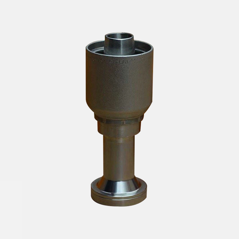
Straight Code 62 Flange
The straight version is the default choice when the hose or tube can run directly into the port face. It adds no side load to the port and gives the shortest assembly length.
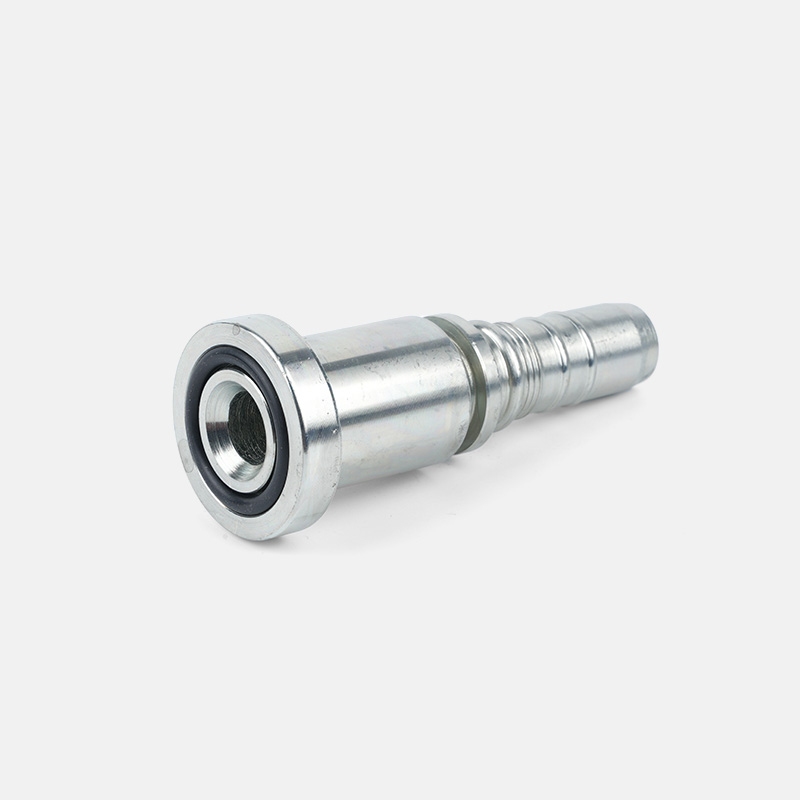 Straight SAE Code 62 Hydraulic Flange FittingFor direct hose or tube runs into a port face, this straight SAE J516 flange supports up to 6000 psi and avoids added side load.View Product →
45-Degree Elbow
When there is a modest change of direction, a 45-degree elbow keeps flow losses low and often saves you a second fitting in the line. It is a common pick for pump and motor ports where the hose has to ease away from the machine frame.
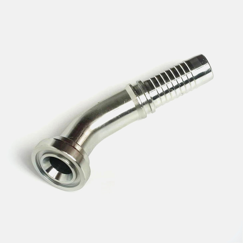 45-Degree SAE Flange Elbow for Hydraulic HoseWhen routing needs only a modest change of direction, this 45-degree SAE J516 flange helps keep flow losses low and may reduce extra fittings.View Product →
90-Degree Elbow
The 90-degree elbow handles tight routing around structural members. Watch the bend radius behind the fitting, because an elbow that lets the hose rub the frame is usually worse than a longer hose run.
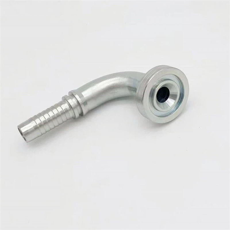 90-Degree SAE Code 62 Hydraulic Elbow FlangeFor tight routing around structural members, this 90-degree SAE J516 Code 62 elbow fits one- or two-wire hoses and handles up to 6000 psi.View Product →
Materials, Plating and Seals
Standard Code 62 flanges are machined from carbon steel and finished with zinc plating, usually trivalent chromate, which gives solid corrosion resistance without hexavalent chromium. Stainless steel 304 or 316 is the usual upgrade for offshore, chemical or food-adjacent environments, and zinc-nickel plating is chosen where salt spray exposure is severe.
Sealing is handled by an NBR O-ring, good for roughly -40 degrees Celsius to +120 degrees Celsius depending on the fluid. For higher temperatures or aggressive media, Viton (FKM) or EPDM is the common swap. Temperature deserves more attention than it usually gets: as the system cycles hot and cold, both the elastomer and the steel change dimension, and a joint that was dry at commissioning can start weeping after a few hundred cycles. If that is a familiar story on your machines, our note on how temperature and environmental conditions affect SAE flanges is worth a read.
How to Select the Right Code 62 Flange
- Confirm the pressure series. If the port is a 6000 psi pad, it takes Code 62 heads and Code 62 clamp halves.
- Measure the port and the head. Head outside diameter and thickness settle the question faster than any part number.
- Choose the configuration. Straight for direct runs, 45 or 90 degrees where routing demands it.
- Match the hose or tube size. Dash size must line up with the hose bore and the flange head bore.
- Pick the material and plating. Carbon steel with zinc plating for general duty, stainless or zinc-nickel for corrosive sites.
- Specify the O-ring compound. NBR for standard mineral oil systems, FKM or EPDM for heat or special fluids.
- Check bolt length. Code 62 heads are thicker, so bolts that fit a Code 61 joint will often be too short.
Installation and the Mistakes We See Most Often
- Never reuse an O-ring. A compressed seal that has taken a set will leak, even if it looks fine.
- Keep the port face and the O-ring groove clean. A single chip of swarf damages the seal face permanently.
- Tighten the four bolts in a cross pattern, in stages, to the torque figure in the standard or catalog.
- Do not mix Code 61 and Code 62 heads or clamp halves, even temporarily, to get a machine running.
- Support the hose. Weight and vibration hanging off the joint is a slow route to a cracked flange.
- Check alignment before torquing. A flange pulled into position by the bolts is under permanent stress.
Where Code 62 Flanges Do Their Best Work
The 6000 psi series is standard equipment wherever pressure is high and downtime is expensive: mining drills and shuttle cars, excavators and wheel loaders, agricultural implements running high-pressure implement circuits, offshore winches and deck machinery, hydraulic presses, injection moulding machines, steel mill equipment, and test benches that deliberately push components to their limits. In all of these, the four-bolt flange does the same job it has done for decades: it holds a high-pressure seal with parts that are easy to inspect and quick to replace.
Sourcing Code 62 Flanges
We have been making hydraulic connection parts since 1999, first as a manufacturer and now through our export arm, Zhuji City Jiangru Import and Export Co., Ltd., shipping to Italy, Spain, Brazil and more than twenty other countries. Code 62 flanges in straight, 45-degree and 90-degree forms sit alongside the Code 61 and Supercat ranges, so if your machine mix spans more than one pressure series, you can consolidate the order. Carbon steel with trivalent zinc plating is our standard stock finish, and stainless steel or special O-ring compounds are available when the application calls for them. If you are unsure whether a port takes Code 61 or Code 62, send us the head dimensions or a photo of the port and we will tell you straight, then quote accordingly. You can start from our hydraulic SAE flange range or send drawings for a specific hose assembly.

Custom hydraulic accessories
From concept to production, we can create the products you want
Products
Contact Information
-

Tel: +86-159-6851-8588
-

E-mail: [email protected]
-

Add:Zhu Jia Station Village, Diankou Town, Zhuji City , Zhejiang Province, China
