


Language
ENG
Enter Keywords...

NEW

How Do You Choose the Correct Size of Hydraulic Hose Connector?
 2026.05.25
 industy news
Choosing the correct size of a hydraulic hose connector comes down to four core parameters: hose inner diameter (ID), working pressure rating, thread type and size, and fitting end configuration. Get all four right, and your system runs safely and efficiently. Miss even one, and you risk leaks, pressure loss, or catastrophic failure. This guide walks you through each factor with practical examples so you can make the right call every time.
Start With the Hose Inner Diameter (ID)
The most fundamental measurement is the hose inner diameter, which must match the connector's bore size exactly. A mismatch — even by 1/16 inch — creates turbulence, restricts flow, or causes the fitting to blow out under pressure.
Hydraulic hoses are commonly sized using the dash number system, where the dash number represents the hose ID in 1/16-inch increments:
| Dash Number | Hose ID (inches) | Hose ID (mm) | Typical Application |
|---|---|---|---|
| -4 | 1/4" | 6.35 mm | Low-flow pilot lines |
| -6 | 3/8" | 9.52 mm | Medium-pressure return lines |
| -8 | 1/2" | 12.70 mm | General hydraulic circuits |
| -12 | 3/4" | 19.05 mm | High-flow main pressure lines |
| -16 | 1" | 25.40 mm | Heavy machinery, large cylinders |
Always measure the hose ID with a caliper rather than relying on the label — hose walls can vary by manufacturer, and worn or old hoses may not match their original spec.
Match the Connector to Your System's Pressure Rating
Every hydraulic hose connector has a maximum working pressure (MWP) rating. This must meet or exceed the maximum operating pressure of your system. Industry standard requires a minimum 4:1 safety factor — meaning a connector rated at 5,000 PSI should not be used in a system exceeding 1,250 PSI at peak load.
Pressure Ranges by Application Type
- Low pressure (under 1,000 PSI): Return lines, drain lines — standard carbon steel connectors are sufficient.
- Medium pressure (1,000–3,000 PSI): Most mobile equipment — use connectors rated to SAE J517 or EN 853 standards.
- High pressure (3,000–6,000 PSI): Industrial presses, excavators — require forged steel fittings and crimp ferrules.
- Ultra-high pressure (above 6,000 PSI): Hydraulic tools, jacking systems — need specialized two-wire or four-wire braid hose connectors.
For example, a construction excavator operating at 3,500 PSI needs connectors rated to at least 3,500 PSI working pressure — not just the burst pressure. Never confuse burst pressure with working pressure; the burst rating is typically 4× higher and is not a safe operating limit.
Identify the Thread Type and Size
Thread type is one of the most commonly misidentified factors in connector sizing. Using the wrong thread type can result in cross-threading, seal failure, or leaks even if the connector appears to fit. The four most common thread standards in hydraulic systems are:
| Thread Type | Standard | Seal Method | Common Region |
|---|---|---|---|
| NPT (National Pipe Taper) | ANSI B1.20.1 | Thread sealant / PTFE tape | North America |
| BSPP (British Standard Parallel Pipe) | ISO 228 | Bonded seal / O-ring face | Europe, Asia |
| ORFS (O-Ring Face Seal) | SAE J1453 | O-ring on flat face | Worldwide (high-pressure) |
| JIC (37° Flare) | SAE J514 | Metal-to-metal 37° flare | North America, Mobile equip. |
To identify an unknown thread, use a thread pitch gauge and measure the outer diameter with calipers. For example, a 9/16"-18 UNF thread is JIC; a 9/16"-18 with an O-ring groove is ORFS — they look nearly identical but are not interchangeable.
Choose the Right Fitting End Configuration
Beyond size and thread, the fitting end angle and style determines how well the connector routes without creating stress points on the hose. Selecting the wrong configuration forces the hose into sharp bends, accelerating wear and causing early failure.
Common End Configurations
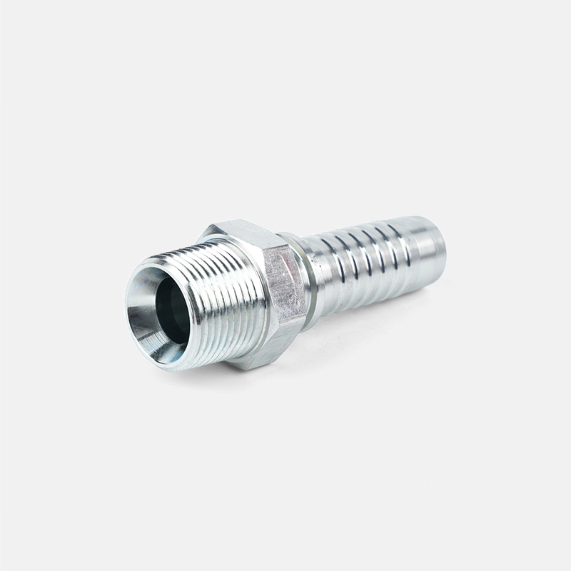
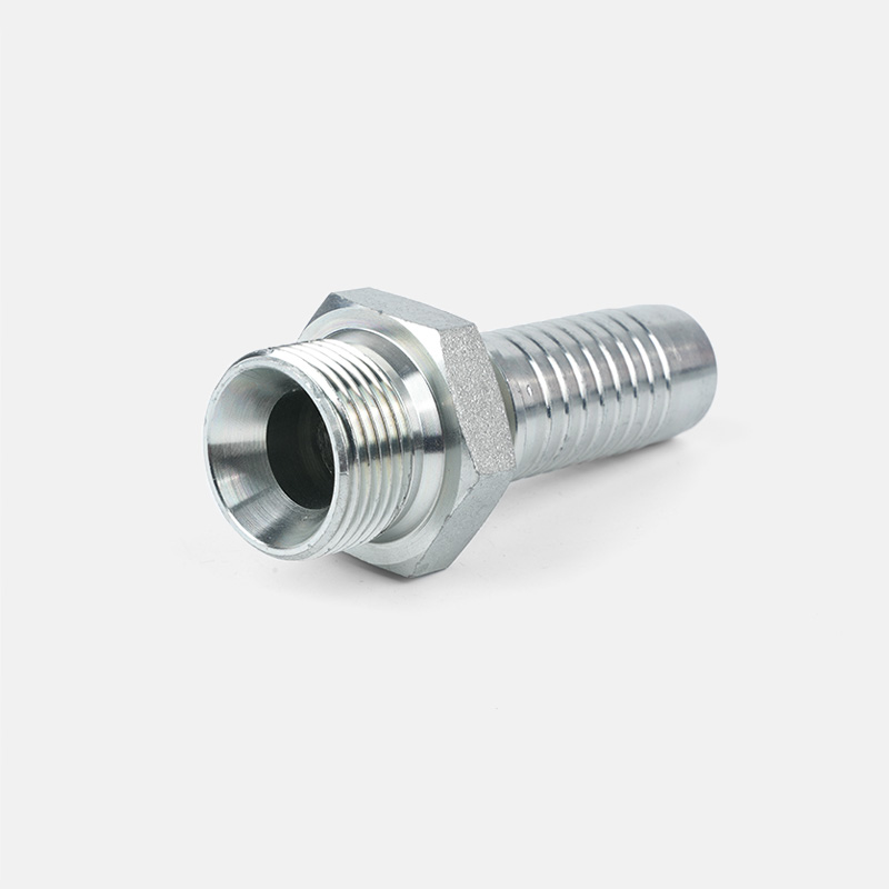
- Straight (0°): Best for inline connections where hose runs directly away from the port. Simple, low-cost, minimal pressure drop.
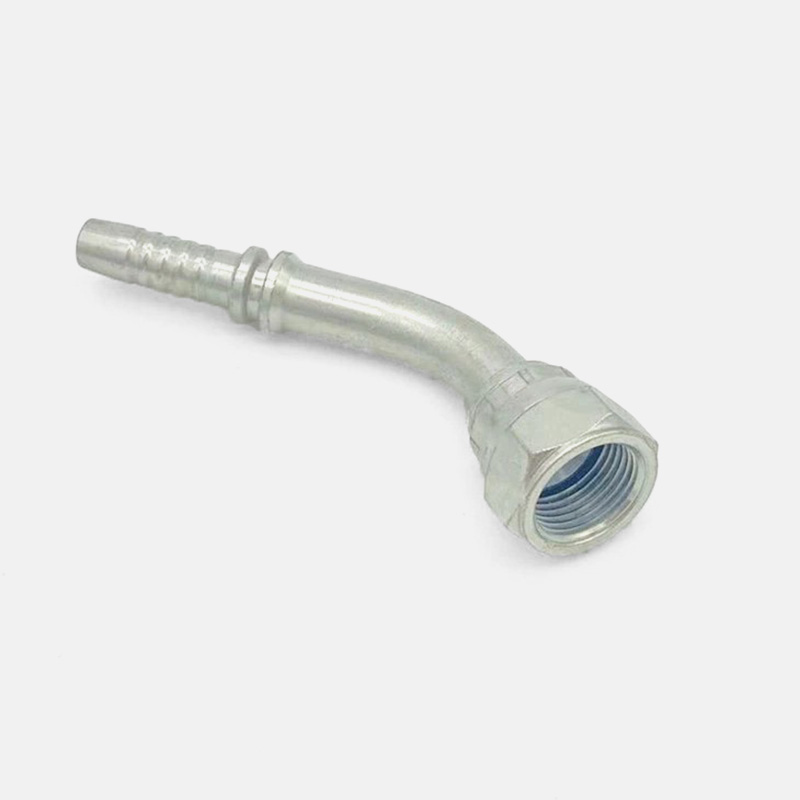
- 45° Elbow: Ideal when space is limited and the hose must turn moderately. Reduces stress compared to forcing a straight fitting to bend.
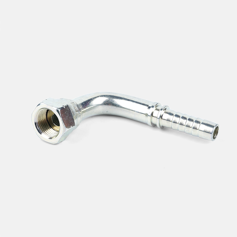
- 90° Elbow: Used in tight installations where the hose runs perpendicular to the port. Prevents kinking in confined machine bays.
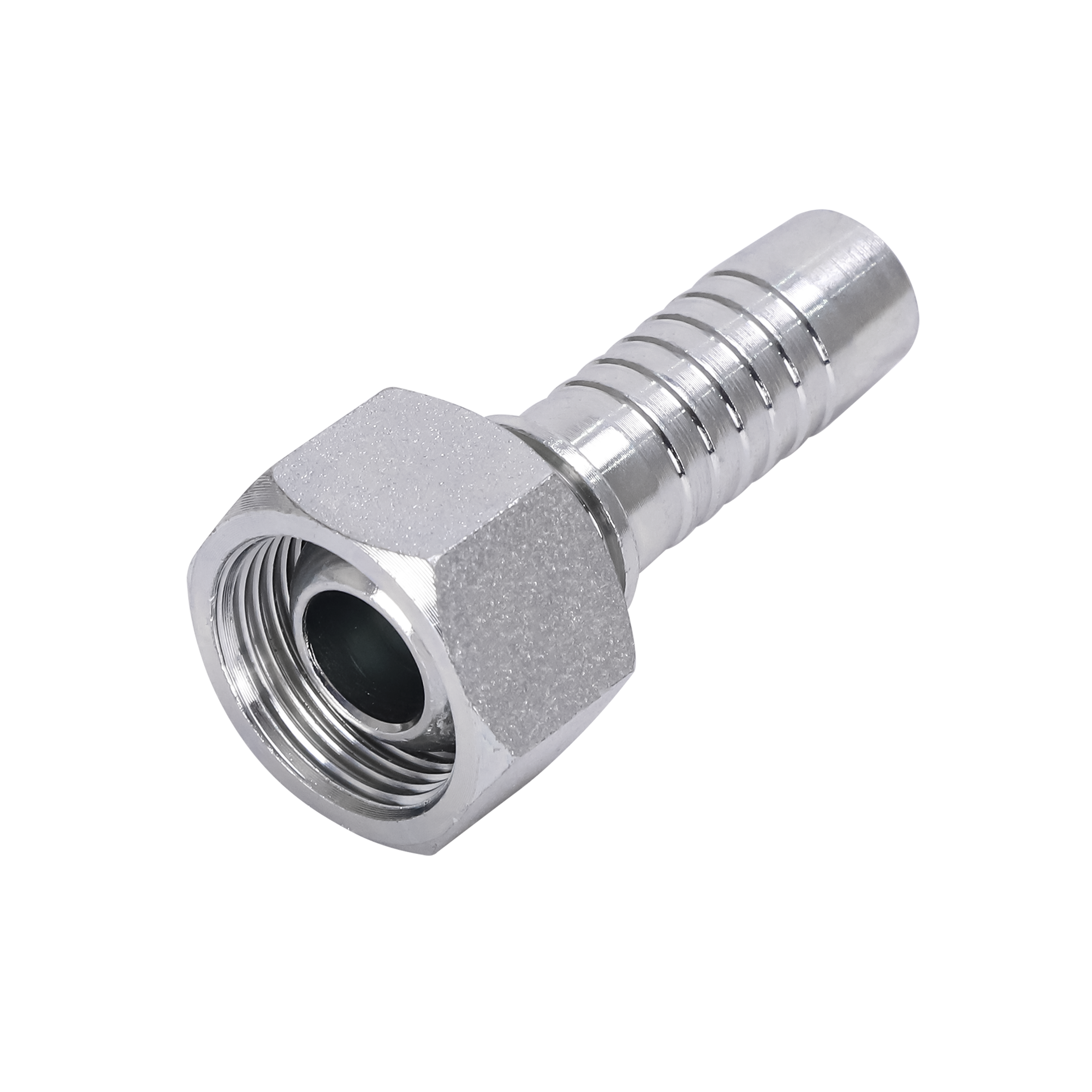
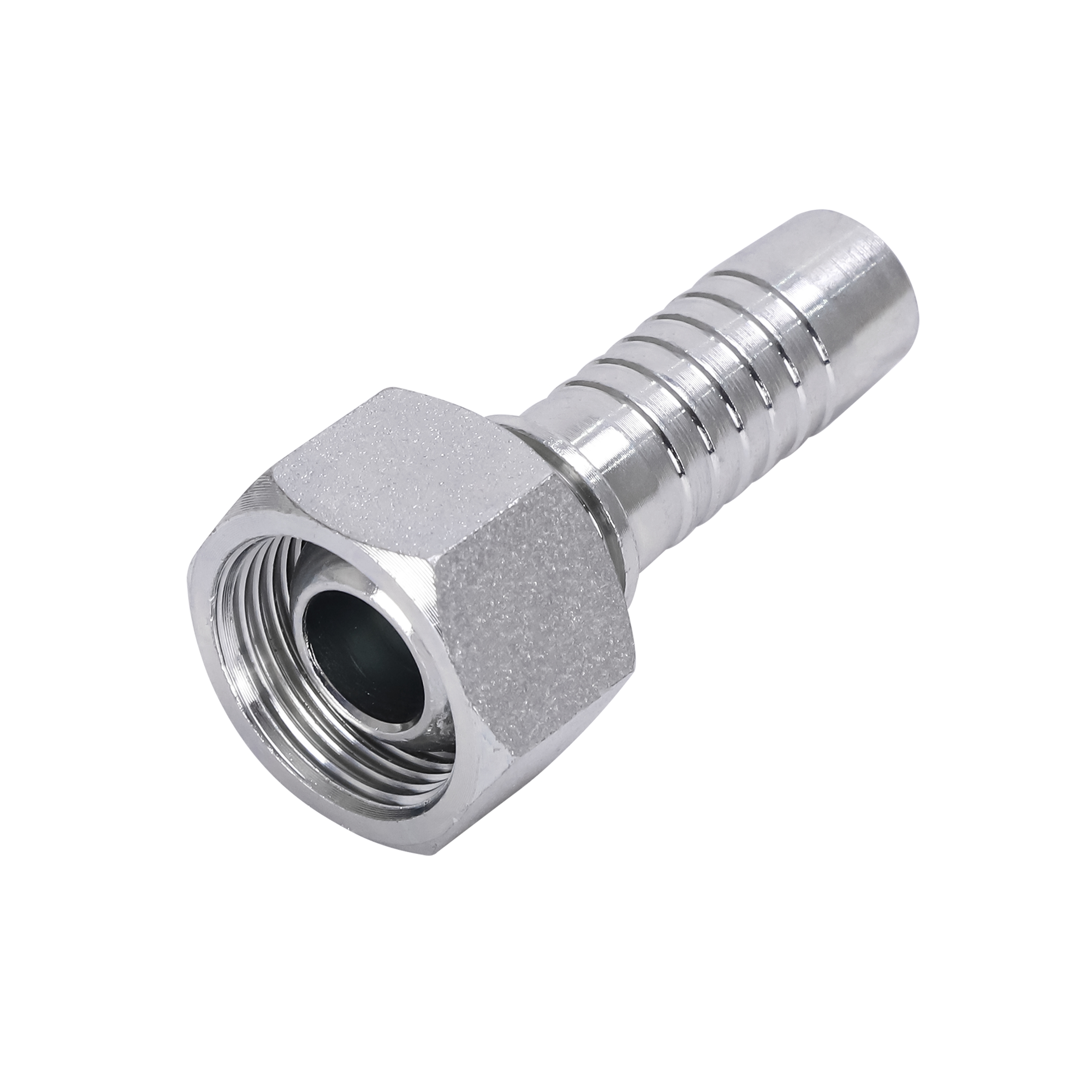
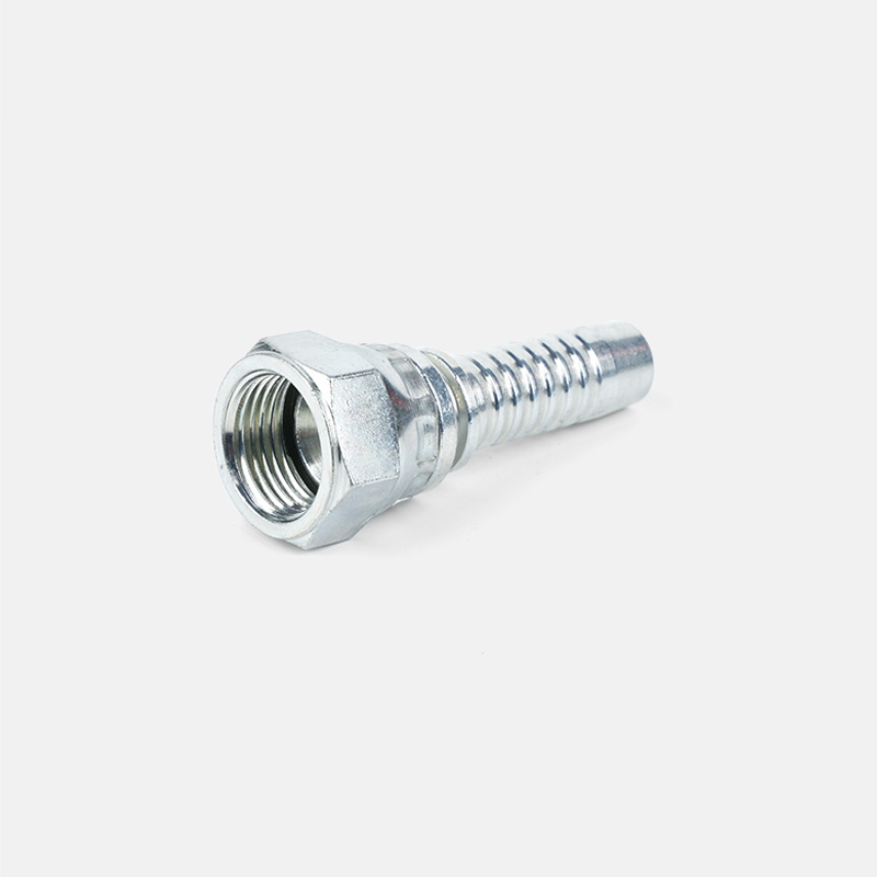
- Swivel fittings: Allow rotational adjustment after assembly — crucial when two connection points move relative to each other, such as in articulated booms.
A general rule: never allow the hose bend radius to fall below the manufacturer's minimum bend radius. For a -8 (1/2" ID) hose, the typical minimum bend radius is around 3.5 inches (89 mm). Violating this causes internal wire braid fatigue within as few as 500 flex cycles.
Consider the Material and Fluid Compatibility
Connector material must be compatible with both the hydraulic fluid and the operating environment. Using the wrong material leads to corrosion, seal degradation, and contamination of the hydraulic fluid — which is a leading cause of pump and valve failure.
- Carbon steel: Standard for petroleum-based fluids. Cost-effective but susceptible to rust in wet or outdoor environments.
- Stainless steel (304 / 316): Required for water-based fluids, food-grade systems, or marine applications. 316 grade offers superior chloride resistance.
- Brass: Common in low-pressure systems with water glycol or mild hydraulic fluids. Not suitable above 3,000 PSI.
- Zinc-plated steel: Economical corrosion protection for general industrial use — suitable for most mineral oil hydraulic fluids indoors.
For fire-resistant fluids such as phosphate ester (Skydrol), standard Buna-N (nitrile) O-rings will swell and fail. You must use EPDM or Viton seals and verify connector compatibility with the fluid's data sheet.
Use the F-M-E-S Method as a Final Checklist
Before ordering or installing a hydraulic hose connector, run through the F-M-E-S method — a practical four-point checklist used by hydraulic technicians to confirm sizing accuracy:
- F — Flow requirements: Confirm the connector bore supports your target flow rate. At 10 GPM, a -6 (3/8") fitting reaches ~15 ft/s fluid velocity — near the upper limit for pressure lines.
- M — Maximum pressure: Verify the connector's working pressure rating matches or exceeds system peak pressure, including pressure spikes.
- E — End connections: Confirm both ends (hose side and port side) have matching thread type, size, and sealing method.
- S — Size and orientation: Validate the fitting angle (straight, 45°, 90°) suits the routing path without stressing the hose.
This method takes under two minutes and catches the most common sizing errors before they become expensive field failures. Over 70% of hydraulic hose failures are attributed to improper fitting selection or installation — most of which are preventable with this simple verification step.
When to Consult a Hydraulic Specialist
Some applications fall outside standard sizing guides and require engineering input. Seek professional advice when:
- Your system operates above 6,000 PSI or involves dynamic pressure spikes exceeding 150% of working pressure.
- The application involves extreme temperatures (below -40°F or above 250°F), which affect seal material selection and connector ratings.
- You are mixing thread standards across an international machine (e.g., a European pump body mating with North American hose assemblies).
- The system uses non-standard fluids such as biodegradable esters, high-water-content fluids (HWCF), or fire-resistant synthetics.
In these cases, relying on a hydraulic connector manufacturer's engineering team or a certified fluid power specialist (CFPS) can prevent both safety hazards and costly downtime.
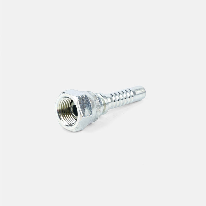
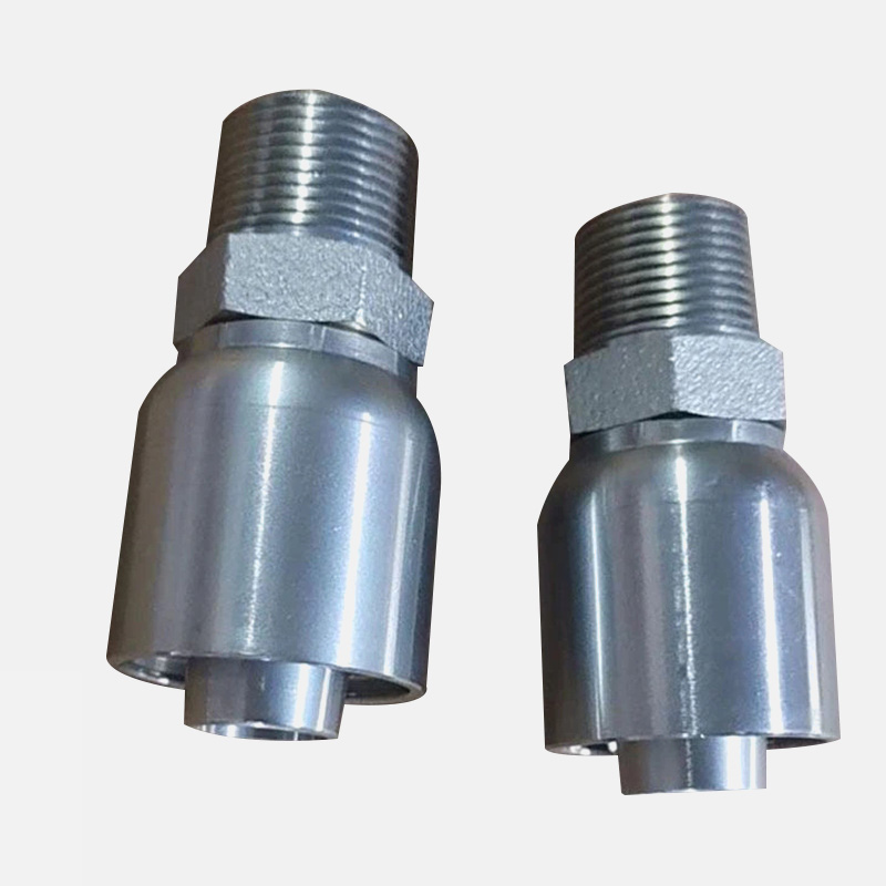
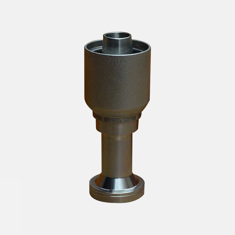
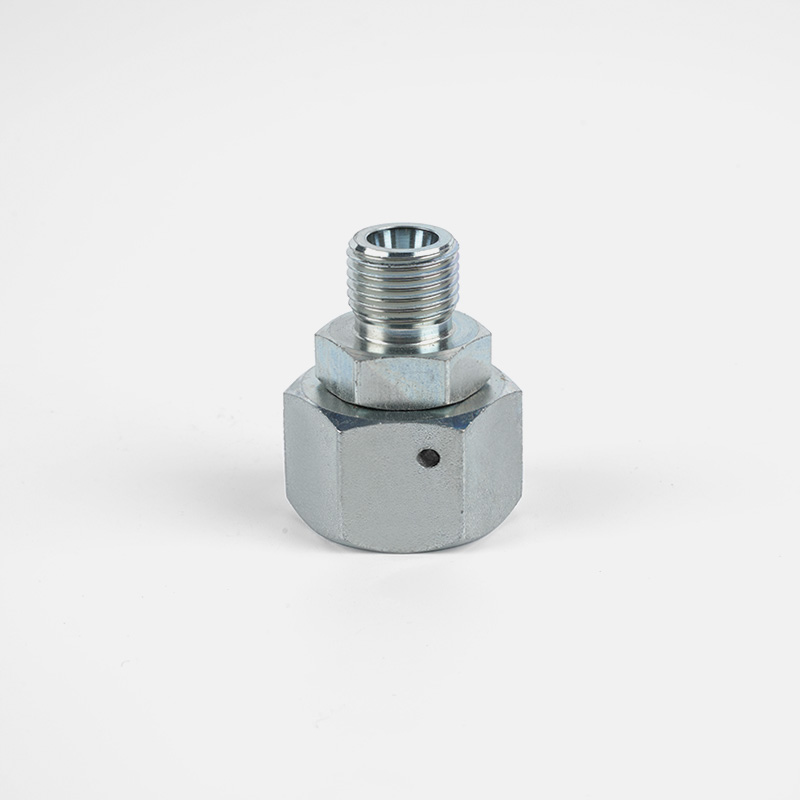

Custom hydraulic accessories
From concept to production, we can create the products you want
Products
Contact Information
-

Tel: +86-159-6851-8588
-

E-mail: [email protected]
-

Add:Zhu Jia Station Village, Diankou Town, Zhuji City , Zhejiang Province, China
